Details: Blank PWM Board - Right Click on any image to save for printing or print entire page
Version 1.00 circuit board legend.
Version 1.01 circuit board legend.
Pin out Charts:
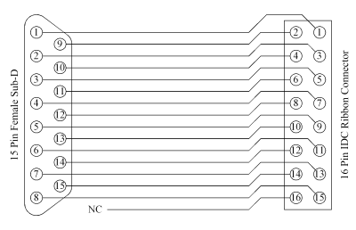
Breakout Port Pinout (Joystick Adapter Port)
|
Breakout Pin |
OOPic Pin |
Description |
|
1 |
21,
22 |
+5V |
|
2 |
21,
22 |
+5V |
|
3 |
26 |
IO Line 31 |
|
4 |
15 |
IO Line 5 |
|
5 |
11 |
IO Line 3 (A2D 3) |
|
6 |
7 |
IO Line 1 (A2D 1) |
|
7 |
2,
23, 24 |
GND |
|
8 |
2,
23, 24 |
GND |
|
9 |
2,
23, 24 |
GND |
|
10 |
9 |
IO Line 2 (A2D 2) |
|
11 |
13 |
IO Line 4 (A2D 4) |
|
12 |
17 |
IO Line 6 |
|
13 |
28 |
IO Line 30 |
|
14 |
21,
22 |
+5V |
|
15 |
21,
22 |
+5V |
|
16 |
19 |
IO Line 7 |
Click for schematic of Joystick Adapter Cable
Left Motor Control
|
Input / Output |
OOPic Pin |
Description |
|
Direction |
34 |
IO Line 27 |
|
Brake |
38 |
IO Line 25 |
|
Speed |
27 |
IO Line 17 (PWM 2) |
|
Thermal Flag |
30 |
IO Line 29 |
|
Current Sensing |
9 |
IO Line 2 (A2D 2) |
|
Input / Output |
OOPic Pin |
Description |
|
Direction |
36 |
IO Line 26 |
|
Brake |
40 |
IO Line 24 |
|
Speed |
29 |
IO Line 18 (PWM 1) |
|
Thermal Flag |
32 |
IO Line 28 |
|
Current Sensing |
7 |
IO Line 1 (A2D 1) |
|
Input / Output |
OOPic R Dual DC I/O |
OOPic Pin |
Description |
|
Dir. |
26 |
36 |
IO Line 26 |
|
Brake |
24 |
40 |
IO Line 24 |
|
Speed |
18 |
29 |
IO Line 18 (PWM 1) |
|
Dir. |
27 |
34 |
|
| Brake Left Motor |
25 |
38 |
IO Line 25 |
| Speed Left Motor | 17 |
27 |
IO Line 17 (PWM 2) |
| +5 Volts | +5v | 21 or 22 | + 5 Pull Ups |
|
Ground |
GND |
23 or 24 |
|
The chart above does not connect the analog signals to the OOPic-R, only required signals for motor control.
Parts List:
| Part Designation | Part Value | Source | Part Number |
| R1, R12 | * 5.6K 1/8 watt (Green, Blue, Red) | Digikey | 5.6KEBK |
| R2, R3, R10, R11, R13 | ** Jumper | Digikey | 929950-00-ND |
| R4, R9 | *** 27K 1/8 watt (Red, Violet, Orange) | Digikey | 27KEBK |
| R5 - R8, R14 - R19 | 10K 1/8 watt (Brown, Black, Orange) | Digikey | 10KEBK |
| C1, C2 | 22 uf 63 volt electrolytic | Digikey | P5190-ND |
| C5 - C8 | 0.01 uf 100 volt ceramic | Digikey | 399-2134-ND |
| F1, F2 | 5x20mm 3.15 amp fuse | Digikey | F950-ND |
| F1, F2 (2 clips need per fuse) 4 total | PCB 5x20mm Fuse holder | Digikey | F063-ND |
| X1 - X3 | 5.08mm 3Pos Terminal | Digikey | ED1624-ND |
| SV3 | 8Pos X 2Row Header | Digikey | S2012-08-ND |
| SV6, SV7 | 20Pos X 2Row Header | Digikey | S2012-20-ND |
| IC1, IC2 | LMD18200T | Digikey | LMD18200T-ND |
| Heat sinks (up to 2 per IC) | 1.0x0.5x1.18 (LxWxH) | Digikey | 294-1008-ND |
| Heat sinks mounting screws | Screws #6-32 | Digikey | H355-ND |
| Heat sinks mounting washer | Lock Washers #6 | Digikey | H240-ND |
| Heat sinks mounting nuts | Hex Nuts #6-32 | Digikey | H220-ND |
* These resistors will determine the scaling factor for current
measurements. See the technical specifications for
the LMD18200T with the
link below.
** These jumpers may be hardwired if the options does not need to be
changed.
R2, R3 jumpers are to allow the OOPic to monitor the LMD18200T for the thermal flags.
R10, R11 jumpers are to allow the OOPic to monitor the LMD18200T for current flows.
R13 jumper is to
allow the OOPic to receive power from the same supply that is powering the Right
hand
PWM driver. (see Important Notes about use of this option)
*** R4, R9 set up the values to use for the centering of the
joystick and may need to changed depending on the
joystick that you choose to
use.
27K ohms worked well with all of the joysticks that we tested.
Assembly Instructions:
|
1. Place the board with the component side facing up and the writing in the correct orientation. |
|
2. Install the resistors first before any other
components. Please make sure to install the for
the proper locations. Be aware of the jumpers R2, R3, R10, R11, and
R13. Two pin headers with jumper plugs or wire may be used for the
jumper locations. (Also see about optional resistor
values.) In version 1.01 the jumpers R2, R3, R10, R11, and R13 have been
relabeled to reflect jumpers in these locations as J3, J4, J5, J2, J1
respectively. |
|
3 Install C5, C6, C7 and C8 into the board. These do not have polarity and can be installed in either direction. May need to bend leads slightly to fit in holes. (One manufacturer fits perfectly while the other is off slightly on lead spacing.) |
|
4.Install the 16 pin header in the middle of the board. |
|
5.Install both of the 40 pin headers on the card edges. |
|
6. install the fuse holders making sure that the fuse stops are
facing towards the outer edges of the board. ( It may be easier to clip
fuse holders onto fuse and insert into board as an assembly before soldering
to ensure proper alignment, but be careful of too much heat on the fuse.) |
|
7. Install the LMD18200's into the board. It may be necessary
to temporary mount the heatsinks to the IC's to get the proper spacing.
(If your heatsinks have mounting tabs on the bottom please cut them off before
using them, and file the clipped edges smooth.) |
|
8. Install the X3 power connector. The openings for the
wires need to face towards the 40 pin connector not the 18 pin
connector. |
|
9. Install the X1 and X2 output screw terminals with the holes
for the wires facing the outer edges of the board. |
|
10. Install the electrolytic capacitors C1 and C2. The
polarity is important here so install carefully, the positive side should be
facing the fuse and the negative should be facing the outer edges of the board
on both sides. In version 1.01 the polarity is marked on the board and
the center and outer holes are connected together and form the ground.
You may use either center or outer edge holes for the negative side of the
capacitor to fit your exact needs. |
|
11. Visually inspect the top and the bottom to identify and
correct any solder splashes or bridges that may be present before powering. |
|
12. Clean and dry board with appropriate flux solvent. Us caution and read instructions on container. Make sure board is completely dry before supplying power. Some flux solvents contain or attack water from the air and will get under components |
Important Notes:
| Version 1.01 has improved readability of the
silkscreen with bolder letters and numbers. Jumper R13 renamed to
J1, Jumper R11 renamed to J2, Jumper R2 renamed to J3, Jumper R3
renamed to J4, Jumper R10 renamed to J5. C1 and C2 moved to allow
more room for heat sinks and different hole structure to accommodate a wider
range of usable components. Schematics remain the same between both versions
1.00 and 1.01. |
| The jumper
in location R13 or J1 on version 1.01, is to power the OOPic's onboard regulator from the same
supply that is powering the right side motor. If this jumper is
installed, the voltage applied to X3-3 should not exceed the limitations of the OOPic.
If you do not install this jumper, you will need to connect power to the
OOPic as normal. |
| When connecting the
40 pin connector on the OOPic to the PWM controller board, care must be
taken to ensure that the Pin 1 is connected to Pin 1 on both boards. |
| The ICs on the PWM controller
dissipate a lot of energy and need cooling if running extended
times under full load, therefore it is recommended that heat sinks be used
with any load over 0.5 amps and 12 volts. The board is designed so
that 2 heat sinks may be used on each IC if the power load requires more
cooling. A general rule of thumb is, if it is too hot to touch for
more than 3 seconds with the index finger- put a heat sink on it. |
| Do not under any circumstances
connect any terminal of the outputs to each other, power, ground or any
other connection, These outputs are floating and must be isolated
from power or ground. Make sure that the motor you are using is not
grounded through the case or you must isolated it so the case is floating
above system ground. Do not parallel the outputs from on channel
with the other channel to increase current, the PWM outputs may not be in phase
with each other and could damage the driver IC's. |
| The center terminal
on the motor connectors are only for shielded cables to cut down on EMI
from the switching currents going to the motors. do not pass any current
through these center connection on motor outputs. (0.001 uf caps may be
added to the inputs of the back of the motors and terminated to the ground
wire middle connection to aid in EMI suppression if there is a problem) |
|
The current feedback from the LMD18200T's are connected to
Pin 7 for right channel and Pin 9 for the left channel. This corresponds
to OOPic's analog to digital channels 1 and 2 of 4. The joystick inputs
corresponds to OOPic's analog to digital channels 3 and 4 of 4 for the X and Y
axis. If current measurements are not needed for the LMD18200T's,
remove jumpers R2 and R10, or J3 and J5 on version 1.01, then the analog channels 1 and 2 can be used for
other analog measurements like a dual joystick. |
|
Optional resistor values may be used for R1, R12 to
determine current scaling for the analog inputs. See the application notes from
National Semiconductor for more information. Optional resistor values may
be used for R4, R9 to compensate for non-standard joystick configurations.
We found 27K worked best with all joysticks we tested. Optional values for
all remaining resistors may be used, these act as pull up or pull down
resistors for power on considerations for the OOPic. Anything from 1K
to 1 meg. ohm will work for R5-R8 and R14-R19. |
|
Throughout these pages we refer to the
right and left motor drivers. These outputs correspond to the X1 and
X2 terminal sides of the board respectively |
| We have not had any complaints as of yet but we noticed
that some heat sinks will touch a via and cause a short on the brake line for the
motor control associated with connector X1. The via that touches the heat
sink is in the center of a triangle between X2, C6, and C2. If you
have problems with the brake causing the motor to run, remove the heat sink, and
place a small piece of tape on the board to cover the via. PICTURE
This via has been moved on version 1.01. |
| We cannot guarantee
the skills that you have in the assembly of this board. It requires the
use of proper tools and techniques to assemble. If you have doubts about
your skills in assembly, please seek the help of a knowledgeable person to give
you a hand in the assembly. Magnevation, Savage Innovations
or anyone else is not responsible for damage to any components that may arise
from the assembly or use of these products. |
OOPic I Programming Sample: Reads values from joystick & controls the left and right motors
| Dim LSpeed as new oPWM
'defines name to first object oPWM speed output
Dim RSpeed as new oPWM 'defines name to second object oPWM speed output Dim LBrake as new oDIO1 'defines name to first object oDIO1 brake output Dim RBrake as new oDIO1 'defines name to second object oDIO1 brake ouput Dim LDirection as new oDIO1 'defines name to third object oDIO1 direction output Dim RDirection as new oDIO1 'defines name to forth object oDIO1 direction output Dim LStick as new oA2D 'defines name to first object oA2D for joystick Dim RStick as new oA2D 'defines name to first object oA2D for joystick Sub Main() 'Start of main
If LStick.MSB then 'This section determins joystick position corrects for non-
If RStick.MSB then 'This section determins joystick position corrects for non-
Loop
'End of do loop
Sub SetUp()
'Beginning of subprogram SetUp
LSpeed.Operate = cvTrue
'Turns on the operate property for LSpeed pwm channel
RSpeed.Operate = cvTrue
'Turns on the operate property for RSpeed pwm channel
|
The above listed program is now available for download by going directly to the new software download page:
This page was last updated June 04, 2010